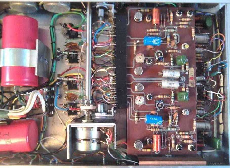
The later mks redesigned the power amplifier completely (including DC output coupling) and mounted the output devices on aluminium extrusions to help dissipation. The large supply electrolytics were however, in the author's view, mounted too close to these.
Although some components can have comparatively high operating temperature ranges, others will not. Elevated temperatures will then reduce the operating life of the equipment, possibly prompting a re-design, but by then reputations can have been damaged. This principle applies to most components, electrical and even mechanical. For example, if the tungsten filament temperature of a 150W general purpose light bulb is reduced by some 300°C by using half of it's rated current, life expectancy can be increased by a factor of a thousand, which can be useful for critical situations. By using two 150W bulbs in series to give the light output of one 100W bulb a newer dimension of reliability is given to the function with a 25% reduction in running costs. In contrast, assuming intermittent use, a respectable brand of power tools, etc, designs all it's motors for a total working full-load life of only ten minutes.
Electronic components come in three grades - commercial, industrial and military, each having a wider operating temperature range than the former, for example with semiconductors the following ranges may be offered: commercial; 0°C to +70°C, industrial; -20°C to +85°C and military; -55°C to +200°C. Choosing industrial grade will increase reliability without bankrupting.
A high-grade electrolytic capacitor might give typical lives of say 1,000 hours (41 days) at 105°C, 10,000 hours (13 months) at 85°C and 160,000 hours (18¼ years) at 40°C. The safe ripple current is also temperature dependent, for example, the same capacitor may quote 140% at 20°C, 120% at 40°C, 80% at 70°C and only 40% at 85°C.
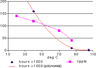
Plotting these suggests a safe operating maximum temperature of 50°C and, operating below the maximum ripple rating given, a life in excess of eleven years.
A commercial 'audio' grade (and thus more expensive!) capacitor, offering inferior performance, might offer only 2,000 hours at 85°C. Allow ventilation around main smoothers since reduced operating temperatures can increase life dramatically.
Rate resistors at twice their operating dissipation. Normally a resistor is fitted close to the PCB, eg;
Those intended to carry high loads should be mounted so that air-flow can occur around them, thus reducing the possibility of hot spots and fire damage to the PCB when a resistor incinerates. For best dissipation, cylindrical types should be mounted horizontally. A minimum distance between the PCB and adjacent components can exceed the resistor's diameter, eg; (2W5 emitter resistors for paralleled output devices, class A)

Notwithstanding structural strength and circuit layout issues, strategically placed large diameter holes through the PCB will aid ventilation. If a low value, high power resistor is not readily available, especially if a non-inductive type is required, higher value, lower power types can be paralleled. For example, if a 0R2, 5W is needed then 10 2R, 0W6 MO types can be paralleled.
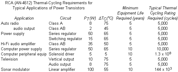
Anticipated uses of silicon bipolar power transistors have been evaluated (1970s) by one manufacturer as follows;
Silicon semiconductor junctions will fail at some 175°C (TO220) to 200°C (TO3), although any plastic package used will fail before this. The life expectancy of such junctions is inversely proportional to temperature, and typically at up to 150°C the life expectancy of a TO220 type halves for every 10-15°C increase. Between 150°C and 175°C it halves for every 5-10°C. To be safe, assume that 100°C is too hot. At the same time, it must be borne in mind that whilst a transistor's maximum power rating is quoted for 25°C, at the maximum temperature this must have been linearly derated to zero.
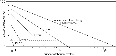
Reducing chip operating temperature will not only increase longevity but will increase safe power delivery capacity. Thermal-cycling rating curves are usually included in a transistor's datasheet. These can be useful in predicting a maximum number of thermal cycles at a given wattage versus temperature change. An approximation for that for a 2N3055 pellet in a TO3 case is given below and plots life expectancy versus thermal stress, eg; if in excess of 100,000 operational cycles involving a 50°C temperature change are required, then a maximum dissipation of some 30W or lower is required. With a Tc of 75°C this would be nearer 14W.
A sudden current surge, say from a short-circuited speaker or associated wiring, can heat the chip to catastrophic levels before the heat-sink can act. Lesser heating events will have a cumulative effect on the chip, in the same way a car windscreen can store stresses over time, and will reduce life expectancy.
Bipolar transistors have a negative temperature coefficient, this means that as they heat up they pass more current, thus getting hotter. An inadequate bias arrangement can exacerbate this. V-FETs have a positive temperature coefficient which means that the current they pass reduces as they heat up. These devices have an inherent safety feature built in. At the same time, because of their construction, V-FETs do not develop hot-spots, which bipolar types are prone to. By increasing the number of output devices, whether bipolar or FET, this heat can be spread, or dissipated, over a larger area.
Some high-power designs require fans, or forced-air cooling, otherwise the case design will become cumbersome. Unfortunately, fans and/or their drive circuits can fail and a secondary thermal cut-out is usually included. One manufacturer made very compact forced-air cooled power amplifiers on a modular basis, which at first seemed like a good idea. Unfortunately, the fans included usually failed leaving the power amps to cook unnoticed until, of course, it was too late. A complex design, with a higher component count, inevitably has 'more to go wrong' than a simpler albeit bulkier one.
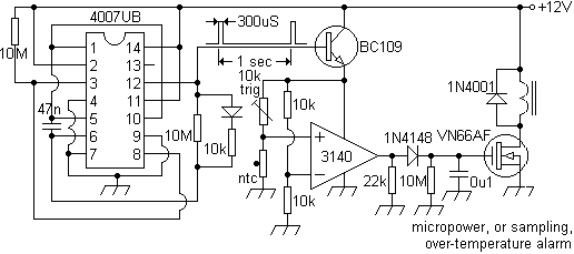
(Modifications to allow micropower sampling techniques for low power systems).
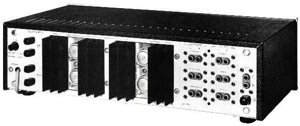
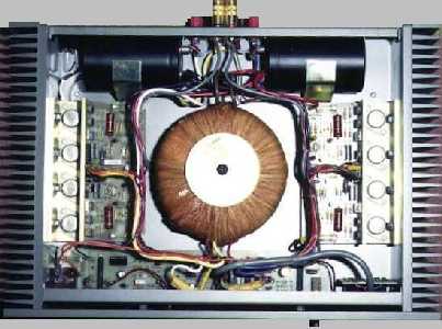
Some professional designs with E-I laminated mains transformers mounted these externally with the heat-sinks. Excellent from a cooling point of view, and helping to reduce hum pickup. The Technics SE-9060, a compact but punchy and reliable favourite, is a good example.
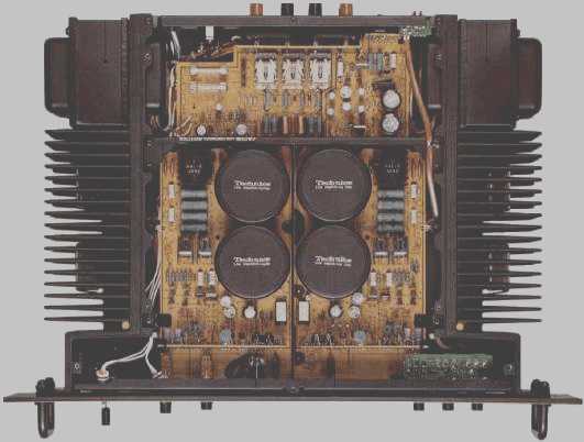
Two of these, each in bridge mode, drove multiple 18" 400W fundamental bass units as part of a highly mobile system some described as 'awesome'. With this, it was hard to disagree. An excellent example of PCB design, typical of the Japanese, that considerably reduces wiring, a similar layout appearing in the later SU-V6.
The older and much larger SE-9600 used massive heat-sinks down it's sides, whilst leaving the centrally mounted mains transformer and smoothers exposed. This design had regulators for the power stages and consumed 960W whilst delivering 185W/4R or 110W/8R with both channels.
The less complex, but eye-catching, class A Nakamichi PA-7, which used 16 TO220 (14 output) devices per channel used a similar form, whilst other manufacturers used bridged configurations to help reduce enclosure volumes, like those used in the Crown MicroTech 1000.
Some smaller cabinet designs, like those of the Quad 303 and the 405, made the front panel the heat-sink. Although sometimes limited, this can be an excellent idea when it is considered how the majority of domestic hi-fi amplifiers and their peripherals are crammed into a small space, with no air-flow around them. Lecson went even further with a design that is still a subject of discussion, and admiration. Always remember that a heat-sink's given rating is that for operating in free air, with no restrictions by cases, cabinets, wiring, etc, and that the dissipation is distributed between all of the devices fitted to it. For example, a 1.2°C/W heat-sink fitted with 4 output devices = 4.8°C/W per transistor.
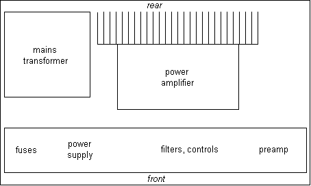
Removing the top panel from a contemporary power amplifier might well reveal a similar layout to that below. This arrangement has been used for fast specialist designs of 50W or more and for professional units delivering hundreds of watts. The two normally flat side-panels are instead large area comb-type heatsinks which, unrestricted in free air, do not require the use of a fan. Deep comb heat-sinks with thermal resistances of <1°C/W are available. Heat from the output devices entering the amplifier case then is much reduced.
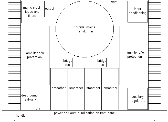
Notwithstanding the heat generated by, say, an amplifier rack, ambient temperatures may impose restrictions on the maximum power it may be safe to draw. Embarrassment can arise if a thermal cut-out trips and a live performance then has to wait for it to reset. Airflow into the case can be encouraged by ventilating the bottom panel, especially if aesthetics or function demand an undrilled top panel. Consideration may have to be given to reinforcing the bottom panel since it may be supporting a heavy component like the mains transformer. Bracing and structural members may be employed and care taken to avoid weakening the case's structure. Ventilation holes may then be made in less critical areas (shaded areas below). Assuming convectional flow, exit slots can be placed along the top of the rear panel allowing air to leave.
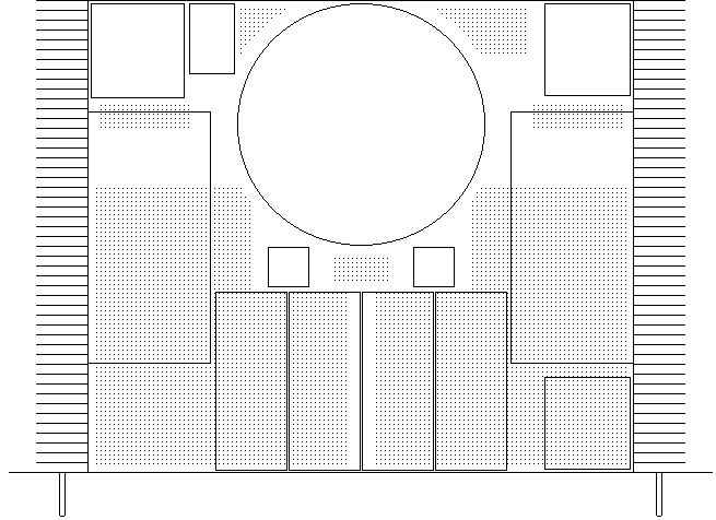
If components, like the smoothers, are stood off the panels they are mounted on, airflow, however slight, will be encouraged. In such a design the height of the case will be determined by the height of the mains transformer which will be mounted flush with it's respective support panel. A gap between the transformer and the upper panel will aid ventilation. If aesthetics demand a slim design then two smaller transformers can be used. To prevent long wiring runs that could degrade performance, switches mounted at the rear of the unit can be actuated by insulated rods that then pass through the front panel.
The Armstrong 732 (only about 50 of which were built) used this layout, the heat-sinks giving a reported rise during heavy use of 10°C. Some raised concerns over limitations of the internal layout and the form of the wiring.
The height of a high-power design will usually be determined by the heat-sink's length. In such a situation the electrolytics can be mounted vertically, reducing case volume.
This configuration of case, using sheet steel, can be assembled quickly. 2-3mm is recommended, although thicker sheet can give an appealingly industrial appearance when used with associated fasteners. Portability is, however, reduced.
Heat-sinking
Heat-sinking is one parameter of which there usually cannot be enough of, some designs appearing to offer very little (take the Leak Delta 30/70). Consider the operating conditions. For example, apart from being hammered will a new design be used in a confined space, in intense sunlight, next to a heater or be left on for days? Unfortunately, a 100% duty-cycle is not usually a commercial consideration.
A class AB output transistor will, as the graphs show, be under greater stress at a 'mid-band' voltage level compared to the upper and lower limits. The greatest stress occurs when the voltages across the load and output device are equal.
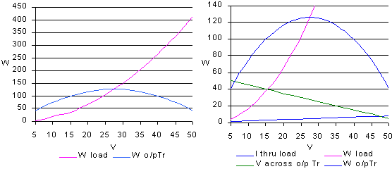
Up to this point the output stage dissipates more energy than the load, efficiency increasing as the voltage across the device decreases. Given listening constraints, headroom, etc, most use will be in the least efficient area. Due to the dropout voltages across the output devices (say 5V), notwithstanding power supply considerations, a maximum of about 90% will be achieved just before clipping.
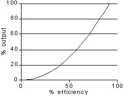
Simply idling, a class A can consume some four or far more times it's maximum usable output. Output stage dissipation is drastically reduced with class D or G configurations and these should be subjectively evaluated if hardware considerations are excessive.
Looking at datasheets it can be seen that TO220 packages offer a typical operating temperature range of -65°C to +150°C and thermal resistances of, say, 1.92°C/W (TIP41), 2.5°C/W, 3.125°C/W and 4.17°C/W. Taking some older, well-known types as examples, the TIP41, 150°C - (say) 25°C ambient = 125°C operating range.
TO3 packages (-65°C to +200°C) can offer from say 1.17°C/W, 1.4°C/W, 1.5°C/W (2N3055) to 1.75°C/W. The 2N3055 gives 200°C - 25°C ambient = 175°C. The chips of these are usually <3mm square, higher rated devices can nearly treble this.
Insulators will invariably be placed between the output devices and the heat-sink, beryllium oxide, anodized aluminium and mica can be used. Thermal compound on mating surfaces will reduce thermal resistance to some 0.4°C/W. Silicone-rubber washers offering 0.5°C/W without compound can be used, but should be replaced when refitting a device. A safe margin to consider would be 1°C/W. However, TO220 devices might give 1.5°C/W with a 0.002" mica washer and 2°C/W with 0.004" (with Dow Corning 340 silicon grease). Larger mounting areas will give a lower thermal resistance, although a hermetic TO3 may not be a better choice than a plastic package since some aluminium cases can fail after some 5,000 thermal cycles, allowing corrosion to occur.
For the TIP41, a maximum operating dissipation then (with a 3°C/W heat-sink) appears to be 1.92°C/W + 1°C/W + 3°C/W = 5.92°C/W , 125/5.92 = 21.1W, considerably less than the 65W rated. With a larger 0.5°C/W heat-sink; 1.92°C/W + 1°C/W + 0.5°C/W = 3.42°C/W , 125/3.42 = 36.5W.
For a 2N3055 with the same heat-sink this would be 1.5°C/W + 1°C/W + 3°C/W = 5.5°C/W, 150/5.5 = 27.3W, compared to the rated 117W. With a larger 0.5°C/W heat-sink; 1.5°C/W + 1°C/W + 0.5°C/W = 3°C/W , 175/3 = 58W.
If 100°C is considered an absolute maximum limit, dissipation levels fall even further to 12W and 13W respectively, for a 3°C/W heat-sink, then 22W and 25W for a 0.5°C/W heat-sink. The same applies if the ambient temperature is higher.
With a 6R load, a transistor will dissipate some 26Wmax in an output pair running from a supply of ±25V, some 38W with a supply of ±30V and some 127W with ±55V. An averaged 'duty-cycle' of 50% can be assumed, but may be meaningless considering signal content. Similarly, a load's frequency dependent reactance can impose conditions far in excess of an output device's designed capabilities.
Given that the figure for a TO3 has an extra margin, it can be seen that two, or even three, TO220 packages will have a smaller PCB footprint than a single TO3 and will be easier to mount. Paralleled devices can be spaced quite closely together on a heat-sink since there will be a distinct drop in chip operating temperature, which is after all the object of the exercise.

Newer bipolar transistor designs, like the MJL3281A/MJL1302A (TO-264) complementary pair, can offer a vast improvement on older designs. Typical specs for these devices include ratings of 200V, 200W, hFE 60-175 (45min), fT 30MHz, Rjc 0.7°C/W. Devices like these should be considered for new builds and upgrades.
A rough rule of thumb balancing cost versus performance appears to recommend the use of output devices whose maximum ratings total about five times the amplifier's output power.
With 6 V-FETs, say, each with a maximum rating of 125W, totalling 750W, a reasonable maximum output of between 125W and 187W seems feasible. Assuming an AB output and an averaged 60% efficiency, heat output can be expected to be between 83W and 124W. Heat-sinking should then be rated at 0.8°C/W in free air, or less. This can be derated in proportion to a reduction in supply voltage/output power, eg: 1.6°C/W for 50-75W and 3.2°C/W for 30W output. For stereo use, another rough rule of thumb gives 2.5°C/W for a 100VA transformer, 5 for 50VA and 1.2 for a 200VA, etc. Ideally, and where feasible, design for a continuous DC output.
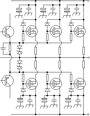
A similar hardware layout can be used for PWM implementations involving paralleled output pairs and/or those utilising Paralleled Phase Shifted Carrier Pulse Width Modulation, or PPSCPWM, which can potentially offer higher output handling using smaller output devices and a virtual absence of heat-sinking by comparison.
Most good quality systems appear to give a sufficient domestic output at 3W, or less, per channel and to observe a ratio of 20:1 or more between the maximum power handling available and that used to obtain a satisfactory sound output, 50-75W appearing adequate. However, smaller designs cannot be underestimated, if built well.
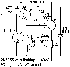
A method to load limit a 2N3055 to 40W is given below but is unsuitable as an audio output stage.
Output transistors are often mounted on an 'angle-bracket' which is then bolted to a heat-sink. This can be unavoidable with TO3 cases which are then soldered to the PCB, but can concentrate heat around the output devices, especially if the bracket is thin and/or has been bent to a right-angle. This last may surprise but is caused by the deformation of the metal's crystals offering a higher thermal resistance. If resource permits, this bracket should be as substantial as possible and ideally be milled from copper, although extruded aluminium is often used. Beryllium is not recommended however, despite it's use in electronics as a heat transfer medium.
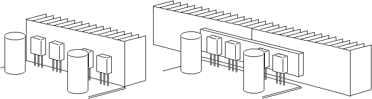
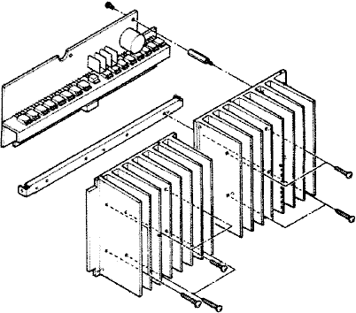
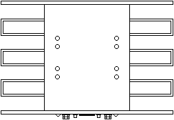
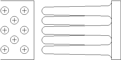
A common arrangement is for the heat-sink to be attached to the back panel, flat-pack style packaged output devices can then be secured to this via screws through the panel, see below (back panel omitted for clarity).
An increased rate of dissipation can be achieved with two heat-sinks, a more even 'spread' obtained with a 'pillow' between the output devices and heat-sinks. This can be copper (5mm or more thick) and have a mounting face similar in size, but smaller than a single heat-sink's mounting face. An arrangement like this can be used if a common heat-sink is used in a stereo design, or if high-power handling is a priority, thus aiding disspation along the heat-sink's entire length. Apply thermal compound to all mating surfaces. With comb-type heat-sinks in free air apply heat-flow contrary, or perpendicular, to vane orientation, which should be vertical, as shown.
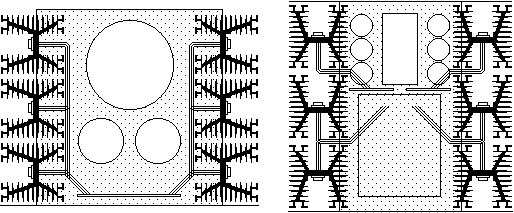
From the above illustrations it can be seen that the outermost output transistor's mounting screws are obscured by an electrolytic capacitor. An axial type, although having a greater PCB footprint, might be a better choice than a radial one. When designing a PCB bear these aspects in mind in order to avoid further unnecessary disassembly when required. Similarly, even a slight gap between the PCB and heat-sink will promote air-flow around the output devices. The solution below, though compact, does not represent the best dissipative layout.
For example, all of the components on the PCB will be subjected to the temperature rise emanating from the output devices. During the design process, this will probably not have been taken into account and, as a consequence, the resulting failure rate can then be high and/or instabilities can arise as commercial grade components are run at or near their thermal limits.
Sometimes a heat-sink's physical design lends itself to, or inspires, an innovative or eye-catching case. High-power industrial types can be an example. Keeping things simple, however, is often the key to a design becoming reality. Water-cooling, for example (necessary for some transmitters, X-ray machines and fashionable for overclocked PCs), can introduce far more problems than it solves.
In a similar vein, two Class A designs used heavy-duty radiators in layouts like those shown below.
In each case, 6 off Redpoint NV115-1 type heat-sinks offering 0.5W/°C were used. This profile, in larger form, was intended for flanged 200A+ thyristors (which had leads fitted and were used on milk floats, fork-lifts, etc) and not for T03 packages. In these amplifiers a considerable proportion of the fins are encased and/or obscured by the enclosure, reducing the airflow and efficacy of the heat-sinking by a considerable margin thus negating much of the reasoning behind choosing these types. The output devices (and regulators in one case) then have to be connected to their respective PCBs by long lengths of wiring, a 'warm' invitation to instability problems, RF pick-up, etc.
It is assumed that these types were adopted for their low thermal resistance, although an element of overkill was evident in one design, the input capacitor being rated at 630VDC(!) whilst those components that followed were of a much more modest 'normal' scale. At the same time, in both designs, considerations relating to mains filtering and soft-starting for the large-value capacitor banks were completely absent. Given that one of these amplifiers is required per speaker, with a usable output of 60W in one case and perhaps a quarter of that from the other with everything running flat out, the author would adopt the form shown earlier not only for the reservations stated, but also on grounds of reduced cost and bulk.
By contrast, a layout used for another amplifier, using machined plates and rectangular section tube aluminium, presents a more efficient, and pleasing aspect.
Nevertheless, a perhaps faulty assumption is made that simply because the mode of operation is class A, everything must run hot.
Many amplifiers assume the general shape of A below which doesn't always have to be the case.
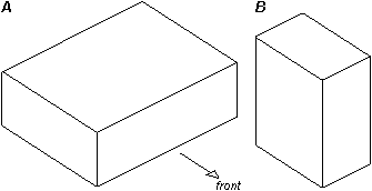
Sony experimented with cylindrical radios and made some smaller integrated amps having the form of B in the sixties, which, in use (bookshelf), made greater ergonomic sense. Notwithstanding the limitations set by cooling requirements (for example, in B the sides can now present a large possible heat-sinking area), this in itself can be an area of study, eg;

A very efficient and substantial radiator from the '70s (cast aluminium, Crimson Electrik) used 'fingers' instead of fins.
Class D amplifiers
Power Supplies |
Protection |
Distortion |
Dimensioning a design |
Setting up an audio amplifier
Contact me at paulkemble@hotmail.com
especially if you want additional content to this page
or if you find
any links that don't work. Don't forget
to add the page title or URL. Take care!
Back to index, sound, tips or home.