Setting up an audio amplifierThe trepidation and chance that some designers report when powering up a new design can be avoided by applying the precautions one can use when powering up a power stage repair for the first time. At all times, before attaching instruments and handling components, first switch off the unit and discharge the electrolytics in the supply via a 15R, 5W resistor. Take care to discharge across the capacitor's terminals, and not to chassis.
All tools should be insulated and care taken when moving tools around inside an amplifier; the metal shaft say of a screw-driver falling on a live supply and power stage can result in much consternation and expense, and in a very short space of time. One chap, who did this after nonchalantly waving a screwdriver over a brand new unit, opened out of curiosity, was upset to find that human-induced faults are generally far more complex and costly than 'natural' ones.
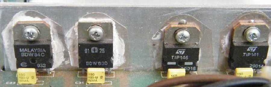
Before even considering re-applying power one must consider whether the standard of re-construction is adequate. Below, in a Lecson Stereo application of the TDA7250 dual audio drivers IC, it can be seen that the original heat-sink has been replaced by angle aluminium, and that the output devices are now mounted vertically. Insulating washers are doubled up or misaligned giving a danger of short circuits to chassis and new mounting holes have had to be added to accommodate short transistor lead lengths.
This might indicate recycled output devices as can the dissimilarity between the transistors used. The heat-sink compound could have been more evenly spread, any excess being removed by a cotton bud. At the same time, new B to C capacitors (WIMA FKC2 series?) have been fitted. These last, more suitable for filters and other low-level circuits, this author would have rated at 200-1kV and 105°C, ceramic or mica.Similarly, the otherwise satisfactory re-build of a RSD 800b was ruined by the output and driver's transistors mounting screws being overtightened then breaking the mounting socket's plastic isolators and creating gross short circuits between the positive supply rail and the output to chassis.
Ideally a variable mains transformer will be used to bring power up slowly. It is more likely than not, however, that such a device will not be available, especially when needed.
Say a class AB power amp of unknown origin and use is blowing fuses and little else. Static tests (without power) reveal a short-circuited output transistor and driver. Discolouration of an associated resistor indicates over-heating and, because the output has shorted to the supply rail, the DC blocking capacitor in the feedback loop can be expected to have been stressed. Wiring a 60W mains light bulb in series with the mains transformer can prevent further damage occuring when power is applied. The bulb can be expected to flash briefly on switch on and output voltage measurements can be made, but if it remains lit is indicative of further unresolved issues, possibly in the power supply.
Replacing the damaged components, no short-circuits are then obvious and readings appear to be normal, so it is time to apply power. Most commercial designs will have an arrangement similar to that below;
Replacing the fuses and simply switching on may not be helpful if, say, there is still an overlooked problem with a differential pair or class A pre-driver, notwithstanding poor constructional standards. To save wasting fuses, time and possibly those components just replaced, it is wise to restrict the incoming current. Replacing the fuses with resistors enables non-destructive DC and listening tests to be conducted. Instead fit 100R, 5W resistors in place of the fuses.
With the speaker load disconnected, apply power (via the resistors) whilst monitoring the output with a DC meter which should settle quickly to about zero (±10-50mV is acceptable, anything exceeding ±0.5V is not). Allow to settle for about 10 minutes and if all is well ie; nothing is getting warm and the output DC is acceptable, set up quiescent and offset, then switch off. Connect the monitor and with the amplifier driving a high impedance speaker load a suitable input signal can be monitored for distortion. Experience has shown that if a decent signal can be heard then the amplifier is a runner. A 'scope, if available, can be used to confirm this. Most amplifiers will run with 100Rs, however, in some cases heavy-duty resistors (2 off, 50R, 20W = each being 2 x 100R, 10W paralleled, or values to suit) can be fitted instead of the 100Rs if, for example, high quiescent currents (class A) are expected. However, in the first instance, ie; checking DC voltage levels, always go for the safest, ie; least current or highest resistance, option.Suspect or new output devices/stages can be thus safely run and tested with this arrangement without resorting to prayers and work can continue even when there is an obvious problem. Always have some means of testing a component before fitting it, and if possible have a spare. This may seem extravagant but it must be given that under-spec devices might have been supplied. This was the case with a recent build of a Riedl design which exhibited an unusual clipping condition with poor driver stage transistors. Fakes have been reported, which means that even if it is more expensive at least a reliable source will be able to replace returns, promptly.
If again all appears well DC-wise, there being nothing significant on the output and/or no major voltage drop across the 100R resistors, fit fuses with a smaller value than normal (say 250mA) and re-align the quiescent and offset after allowing the amp to settle for about ten minutes. The circuit position for these will vary, but initially ensure the quiescent is set for maximum current draw by the thermal compensation transistor (and not the output stage!). If a setting is unknown or unavailable, with a small to medium amplifier set to 7mA above that which the rest of the circuit draws, as a first guess. Fine tuning can be done with a 'scope.
Problems still exist if a fuse blows or, say, the resistor in the output RC network starts 'cooking' (oscillation). If no 'scope or frequency meter is available, oscillation may be hard to spot (see Instabilities). Oscillation can occur when a test instrument's leads (DVM, 'scope) are applied to the unit under test. To prevent this, load the probe attached to the signal side with a resistor, say 680R. Listen to the amp through a normal load, the object being to ensure no distortion. Be careful not to blow the smaller fuses, which should give an adequate volume. Checking an output by listening through headphones only is not sufficient, since an adequate volume for these may be provided by the driver transistors alone.
If the gods still smile sweetly, replace fuses with normal values and run the amplifier into a normal load until hot. If satisfactory, remove the resistors, after which the amplifier can be boxed up and tested again. Some class As may need to warm-up (20 mins) before meaningful adjustments can be made and may need monitoring and fine adjustment over many hours (say 10) to settle correctly. When the amp has thoroughly 'warmed up', switch off and retighten any fasteners since these might have loosened with expansion.
On occasion, extended power tests are required and it is advantageous for these to be conducted silently. Heavy duty resistors can be mounted directly on to speaker plugs which can then be plugged into the unit under test. A ¼" jack mounting two paralleled resistors (22R, 17W each) proved useful with smaller PAs intended for stage performance. For larger loads, something meatier may be required. A simple arrangement that worked well in dealing with a series of large PAs displaying destructive intermittent DC output swings is shown below;
The combined resistance of the coils gave 6.2 ohms (cold), a minimum intended working load being 400Wrms (8A) continuous (100% duty cycle). A switchable capacitive load offered 'reactance'. A high impedance monitor provided audio out with an AC voltmeter offering visual indication when the monitor was off. A heavily perforated SMPSU case housed the ceramic elements separately from the other components. The whole unit was then mounted stood off a wall allowing continuous free air-flow through and around it. A long length of substantial, but fine-stranded, twin-core mains cable then allowed access over the entire work area, reducing lifting considerably.A 'soak-test' would involve an amplifier running a feed from, say, an FM tuner into the dummy load overnight, below clipping. If a sine-wave or noise was used then the amp would be run at 3dB below clipping. A long lead from the source again reduced lifting.
A class AB output transistor will, as the graphs show, be under greater stress at a 'mid-band' voltage level compared to the upper and lower limits. The greatest stress occurs when the voltages across the load and output device are equal.
Up to this point the output stage dissipates more energy than the load, efficiency increasing as the voltage across the device decreases. Most AB stages operate in the lower half or least efficient area. Simply idling, a class A can consume some four (or more) times it's maximum usable output. It therefore makes sense, when testing a design or repair, to run-in the amplifier at these kinds of power levels, in order to 'stretch' the output stage, in thermal terms. In determining weaknesses, this can be more productive than continuous tests at high power levels, bearing in mind that a 100% duty-cycle is not usually a commercial consideration and that a purely resistive load bears little electrical resemblance to an actual loudspeaker (earlier simulated speaker loads included for a 15 ohms loudspeaker: 15 ohms + 1 mH; and for a 4 ohms loudspeaker: 4 ohms + 0.25 mH, see also here).If measuring power-bandwidths, apply a signal for say 2 seconds with a pause of 5 seconds per reading. This gives time to note the reading, write it down and then re-adjust to the next frequency, without over-stressing the output stage.
The same dummy load can be put in series with suspect loudspeaker units, allowing them to be driven and tested safely. A more elegant approach might mount 50W wire-wound resistors, in parallel, on a 0.5°C/W or less deep-comb heat-sink in free air, assuming that the load must handle the continuous output from the largest transformer available (20 for 1kW at full rating, 40 for 2kW). For these kinds of power levels, air-cooling can have distinct advantages over water-cooling. Wire-wound resistors will fail open-circuit and thus can be safely paralleled.
When fault-finding or installing systems run on lower voltages, eg; automotive, marine, class D, etc, the use of a suitable bulb as a dummy load, whether in series with a suspect amplifier or speaker, can be of considerable assistance. As the load is driven harder, the bulb's filament's impedance rises, then limiting the current through the load.
Such an approach is useful when faced with unknown or dubious loads and can be used to prevent damage to a new or repaired power supply when powering up for the first time. Expensive 'aviation-grade' lamps have been used as an integral part of high-end tweeter arrays, it being cheaper to replace the bulb rather than the driver.One can blow a fortune on test gear, the author didn't. If one is happy to recycle components, quite sophisticated 'lash-ups' can be built for virtually nothing. These can easily have a specification that exceeds that of 'professional' equipment, and, since the components will have been burnt-in can arguably be more reliable (bathtub failure curve). Most equipment is scrapped for the want of one component in maybe hundreds that are still functioning perfectly. For example, a keyboard/synthesizer made redundant by a 'faded' EPROM whose hexdump is no longer available can provide a complete supply assembly including switch, fuse-holder, filter, transformer and supply PSU, complete with regulators and wiring loom thus reducing costs, time and assembly. At the same time, precision components may be used in the D/A convertor or filters, there may be plenty of low-noise opamps and the enclosure's bottom can even be used as a shelf! Redundant tunerheads and large RF/IF cans provide ideal enclosures for preamps and signal sources.
One handy circuit, shown below, was used to locate a short (0µ1F supply decoupling capacitor) between the supply buses on a complex logic board.
A small amount of current is fed into the circuit and the probes are placed on the track a short distance apart. The short is located when the LEDs change, then showing where the current flow reverses. Ordinarily, a lengthy process where tracks would have to be cut and measurements made would be involved.Working with audio meant using, sometimes only occasionally, a number of circuits which were put into an old 19" 2U amplifier case to save clutter. Items included a sine wave oscillator (7Hz-700kHz), frequency counter, reciprocal RIAA filters, two x0-100 low-level amplifiers (HA12017), filter switchable noise source, attenuator, wideband amplifier feeding a fast rectifer and peak detector with variable sample and hold, VU meter, headphone amplifier and their power supplies, signal source's supplies being separate. All inputs, outputs and controls were brought to the front panel, a small patchbay being used to interconnect. Since care had been taken in design and construction, rather than a commercial approach, spec exceeded that expected by a factor of ten or greater, giving useful confidence at very low levels. Apart from some sockets, a couple of ICs and stripboard, everything used, including the precision components, had originated from discarded gear.
Separate units run from 9V batteries can benefit from an auto-power-off circuit, such as those below.
RC networks with very low thermal drift were made by paralleling precision resistors and polystyrene or mica capacitors. By increasing the physical bulk of the elements involved and shielding or enclosing them away from say draughts or heat sources then requires far greater levels of thermal energy to affect specification. Keeping input levels low, even a little airflow around the components in a confined space is preferable to insulating them. Allow a warm-up period of half an hour before taking measurements and drift, for audio purposes, will be negligible (0.1% or less) and most certainly inaudible.Resistors can be matched by using high tolerance types or measuring them. However, it is often sufficient to take, say, four successive resistors from the 'belt' in which they are packaged.
If mounting axial-leaded resistors in an upright position to reduce PCB area, the longest lead should be connected to the least impedance 'seen', thus reducing the area of a 'sensitive' high impedance side. The same can be said of polystyrene caps which if marked at one end indicates that wire is connected to the outermost foil and is then ideally connected to the least impedance. Stripboard can be useful to about 5MHz. Finish board by cutting runs to minimum length required and binding unused strips to ground. Tinning connecting runs can aid identification. Finished and tested PCBs should be cleaned and tropicalised as a matter of course. The acids present in even fingerprints can lead to corrosion, and in the case of enamelled copper wire, insulation failure.
If enclosing or say potting in epoxy to waterproof, bear in mind capacity of cables, if their cores are exposed, to draw water along them.
When gold-plating, a slow dip at low current will give a better and stronger finish than a fast high current dip which can be porous due to gas generation. In other words, 'still' overnight (or longer) is preferable to ten minutes fizzing. A thin smear of silicon grease can be used to mask areas, having cleaned with a weak acid first.
Although Fluke meters are popular, others can give excellent service. My first meter was a very low impedance but very solid and accurate Russian U4312 followed by an Avo 8 Mk3 and two smaller moving-coils which all died by the ignorance of others (a second U4312 met a similar demise). Moral: if someone wants to use your meter because it is better than theirs, say no or make them guarantee replacement. The use of low-impedance meters led to the development, and interest in, low-level, high-impedance amplifiers. A very compact Beckman 3020 (excellent) was followed by an Avo DA117 (which if left for long periods seems to forget what it is) and then the very excellent White Gold WG 020, which has just about everything and is still used today. Most meaningful voltage measurements can be of only two significant figures, three or four significant figures often being superfluous. Always keep a meter in it's case or holster.
A 'scope, preferably twin-beam with delayed sweep, allows much deeper investigations. Second-user sources can provide bargains that are 'run-in'. If testing filters, use with a sweep generator can be helpful. A useful 'Audio Oscillator with Tone Burst' was described by J.T.Tiernan in the October '82 Wireless World.
Distortion | Protection | Power Supplies | Layouts and Heat-sinking | Dimensioning a design Contact me at paulkemble@hotmail.com
especially if you want additional content to this page
or if you find any links that don't work. Don't forget
to add the page title or URL. Take care!
Back to index, sound, tips or home.