JLH mosfet amplifiers
This design many found interesting, despite some serious errors which have been corrected in the diagram below. Transistor types are those used in the prototype.
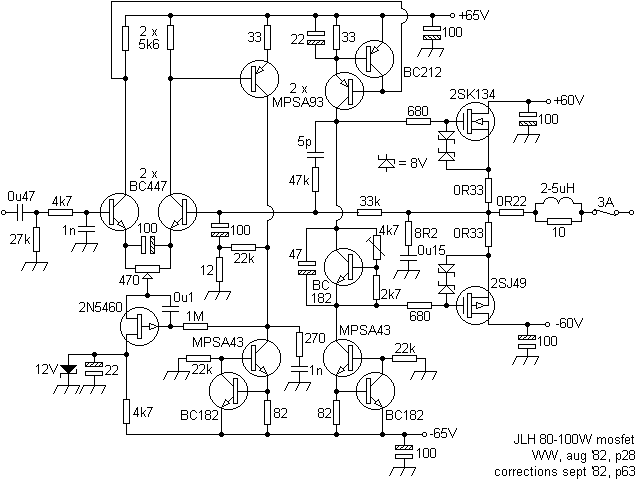
Both channels were fed by a 250VA 50-0-50 toroidal transformer. An 8A bridge rec fed the output devices via 4m7F smoothers and a 1A bridge rec fed the input and drive stages via 2m2F smoothers. The input filter gave a response of -3dB at 30kHz. The pot in the emitter circuit of the input long-tailed pair can accommodate device variation and is used to adjust the output to 0V, ±20mV, the associated FET and zener diode providing isolation from unwanted signal components on the supply line, the 100µF tantalum avoiding loss of open-loop AC gain. The second voltage amplifier (fed from the collector of the inverting input transistor) provides positive feedback restoring the open loop AC gain to 500k from 100Hz-3kHz and a DC negative feedback to the current stabilising FET. Both amplifiers are fed by constant current sources. The RC network between the output and the collector of the first 'class A' amplifier reduces the gain of the power stage at HF and, in other designs, can reduce crossover distortion and the effects of differences in Cbc of the class A driver. The 'variable diode' is not used to apply thermal regulation, the bias pot set to an Iq of 100mA through the output pair. Thermal mating of associated transistor pairs was not permitted by the given PCB layout.
Available power output (8R) varied linearly between 20W with a ±30V supply and 105W running on ±65V.
Oscillograms gave THD readings at 80W/8R of 0.004% at 200Hz, 0.0025% at 1kHz and 0.025% at 20kHz. It was noted that square wave ringing (at 100kHz, 10V pk-pk into 8R/2µF) was considerably reduced without the output inductor. It was this observation that drew the eye of the author, having failed to convince other professionals of it's significance. The protection circuit used is shown below and can be used as an 'add-on' for other amplifiers, providing DC protection and a switch-on delay. Emphasis was put on the use of gold contacts because of silver's propensity to tarnish.
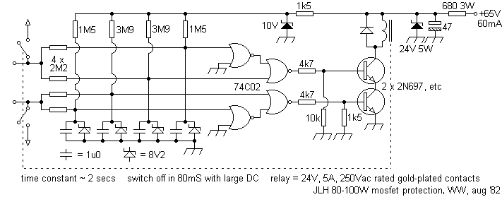
The supply for the CMOS nor gates was derived from the +10V rail and ground. The 1982/3 Modular Preamplifier design, with which this amplifier was intended to be used, was published immediately after.
The 1989 'all'-fet (March, EWW) used fets throughout the signal path and is a very pertinent observation of times and fashion. Maximum power delivery was intended to be 30W.
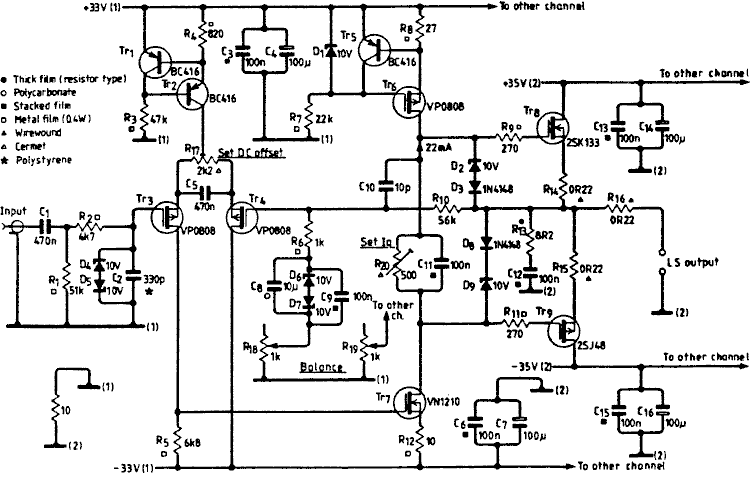
This is useful for a discussion of component limitations and differing fet constructions.
Following on from the design featured in Jun/Sep '84s' ETI, this revised version appeared in May '89's edition as 'the best amplifier you can build' (sold as the Hart K1100 series, last revision noted June '96). Significant aspects included the regulation of both pre- and power stages, the use of current souces and mirrors, and consideration to the types of capacitors used in the signal and feedback paths. The Hart power amp PCBs had a ground plane under the pre- and drive section components.
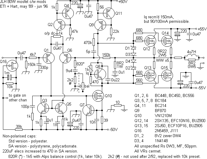
Whilst retaining the clamping and loading of the mosfet's gates to limit self-oscillation, this departed from the norm in a number of areas. Most significantly, a small signal (120V) mosfet used as the class A driver, a paralleled output stage for ruggedness, a regulator offering current-limiting in emergencies and a FET mute, thus negating the use of relays for the speakers. Additional input controls gave versatility and an output inductor was included for 'strange' cables. For stereo types, balance was applied by adjustment of the gain of the feedback network, the 'audiophile' Hart SA version using high-quality Alps pots. This has the effect of altering the lower roll-off as well, eg; 9µ4F+820R = -3dB @ 20Hz, adding 1k results in -3dB @ 9.3Hz.
'Odd' values, as always with JLH, are obtained using easy combinations of standard value components, eg; 9µ4F = 2 x 4µ7F paralleled, 5pf = 2 x 10pF in series.
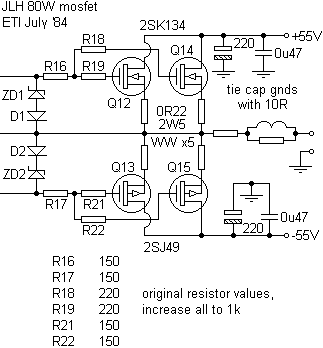
Mods (courtesy of David Huckle) restore additional output gate resistors used in the '84 ETI version that were omitted in the later Hart version. This resolved "a very subtle but different sound... [the] Hart amp definitely did not sound as lucid and fluid... there was a slight hardness or grainy edge to the music right through the scales, on the very best recordings". This might well have represented an oscillation problem.
The use of an active regulator for the power amps (as a separate module) was driven by the low impedance offered. To match this in terms of µF, one would require capacitors of 1F at 80V, a less than compact, inexpensive or reliable solution. Smaller main smoothers can then be specified. One can consider, for economy, regulating the pre-driver's supplies only, but by necessity the power stage's supply will be commensurately bulkier for similar performance, and arguably less reliable, Hart pointing this last out by not guaranteeing the electrolytics they supplied (whatever grade) beyond three months. With given functional lives of 2-5,000 hours, perhaps upgrading to a superior (and cheaper!) industrial grade would have helped.
One must always be mindful, however, that increasing the component count will invariably increase the rate of component failure since there is more to go wrong.
Feeds from the outputs can initiate shutdowns under adverse conditions, before damage to the amplifier, or speaker, can occur. Premature shutdowns, due to infrasonic signals can be reduced by raising the amplifier's lower (inaudible) roll-off.
The later (Hart) combined regulators and cut-out for both stereo and monobloc versions are shown below. Latest revisions are included and the 3nF HF stabilisation caps introduced are retained.

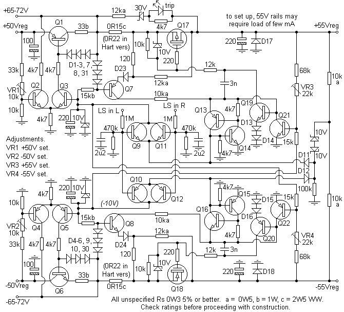
The original regulator is shown below. Due to the vulnerability of Darlingtons, under short-circuit conditions (failure of MJ2501 in Q17 position which would then take out Q7 and the 12k resistor feeding it), mosfets were substituted and other amendments made improving performance and reliability.
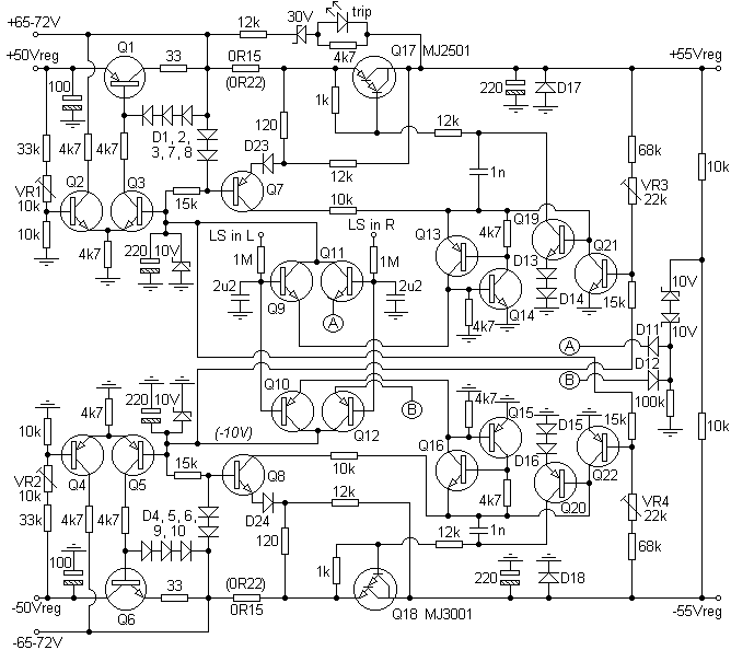
In the Hart SA version some electrolytic values are doubled and in both types the high current rail's current sampling resistor is increased from 0R15 to 0R22 to give a higher safety margin. This then reduces maximum available output power, especially with a stereo layout. The PSU output mosfets are mounted on the PSU chassis with no additional heat-sinking. Best layout in Hart form considered to be monobloc (master or slave).
Although an apparently complex but genuinely concise and compact overall system, no thought had been given to the accommodation of the filtering of mains borne noise, essential with an efficient transformer, which should be screened. Some form of inductive filter (6A Schaffner FN321 fitted chassis) and the use of varistors is recommended. 'Transience' was an area found to be the failing of a number of otherwise 'nice' JLH kits (Hart and Powertran), which then required a fair amount of attention to sort out. A bit of a shame, but if one wants to hear excellence, one doesn't want to be startled by previously inaudible central heating. If, for example, a customer is taking the trouble, and expense, to employ a specialist design with 'special audiophile grade components', why spoil the sheep for a ha'porth of tar?
The two (Hart) PCBs could require attention before use. PCB 1140-3 (PA) was cut too wide and had to be trimmed. PCB 1150-3 (PSU) had to having a missing wire link fitted. Another PCB design could give consideration to the proximities of associated transistor pairs so that the thermal mating of these is possible.
At the same time, 10nF, 1kV ceramics could have been fitted across the mains switch contacts, transformer primary and secondary, and the rectifier diodes. The author would have included a soft-start to reduce power-up stresses, a privately held major contributor to component failure.
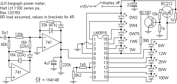
Power meter for same (3dB steps)
and some input switching options offered, although it is recommended that both sides of any coupling capacitors be grounded via high value resistors to prevent switching 'clicks'. Similarly, it must be understood that a mono switch will negate the action of any balance control that precedes it.
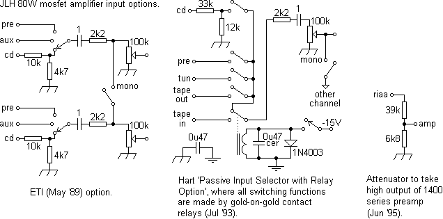
Input FET has been utilised to reduce input signal, by internal temperature sensors, for long-period usage. Construction is eased and connecting media reduced if a single PCB accommodates both the PSU and a PA. A second PA, if desired, can easily be piggy-backed on top of the first.
Overview: very nice, one of the best expressions of a power amplifier for private/domestic needs seen with plenty of contributory work (although more copper could have been left on the PCBs) and it sounds fine. In the right hands! Nice one though, John.
Requests for data, layouts, etc, may meet with disappointment, the quality of the sources being poor, this being the very incentive to produce this page. Alan Jackson offers PCBs for this project at apj audio.
Matching pre-amp items.
JLH Class A (1969, 1996) amplifier.
Contact me at paulkemble@hotmail.com
especially if you want additional content to this page
or if you find any links that don't work. Don't forget
to add the page title or URL. Take care!