Practical Electronics Gemini and Orion.

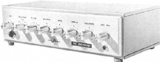
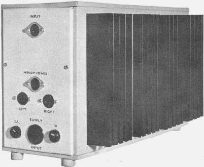
A sophisticated self-build approach was offered by Gibb's and Shaw's 1970/1 PE Gemini, with the preamplifier housed separately from the power supply and power amps. This compared favourably to, say, Quad amplifiers designed at the same time, with a saving in cost (preamp - £17, main amp - £28).

The first power amplifier stage provides all the voltage amplification at low power levels, the cascode arrangement providing a means of eliminating 'early effect' distortion by means of limiting the current under short circuit conditions (a similarity has been seen in other later designs, like the 1988 Cyrus 1). Note the relatively low impedances of the feedback network (increasing the 39R to 82R can extend the bass with little subjective difference in gain, although the 1k5 can be similarly raised to 2k2).


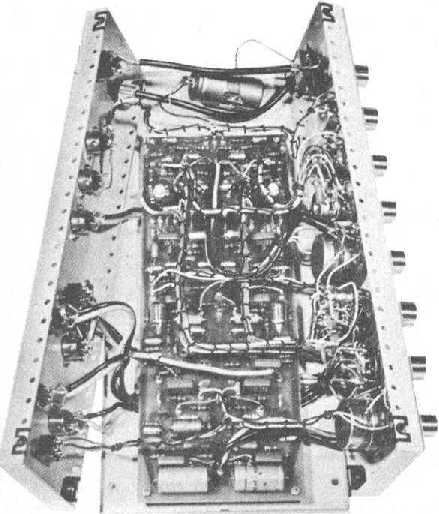
A class B current-limited output stage gave a current gain of 2,000 but a voltage gain below 1. High bias stability was achieved by using fully complementary compound Darlington output pairs acting as two stage feedback amplifiers, any change in the junction temperatures of the output pair being reduced by the loop gain of the stage, about 7. A fully-complementary output stage overcomes the drawback encountered with some quasi-complementary designs where the transfer characteristic becomes markedly assymetrical at low signal levels, then contributing to distortion. For this reason, low-level distortion figures are usually absent from an amplifier's specification. 1.5-2mm thick duralumin strips were then used (with heat-sink compound) to thermally bind the (Ferranti e-line) bias and driver transistors together.


With these arrangements, "after sustained operation into a short-circuit with the output transistors running at 100°C case temperature, the bias had changed by only 10mA from the correct figure of 30mA, and it returned to within 2mA of the correct current in less than a minute", which is commendable even by today's commercial standards. Similar topologies are seen in the next year's Texan and much later designs.


Two heat-sinks were used (1.1°C/W Redpoint 6W/1 or equivalent), one for all of the output transistors (stereo) and a separate one for the regulator's output device. These were mounted on the outside of the PSU/PA case allowing a very free airflow around them.


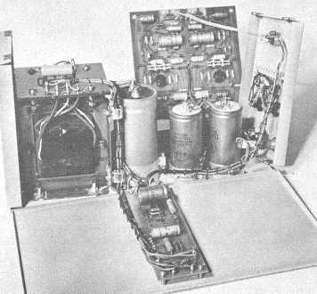
A substantial mains transformer was specified, the regulated power supply providing 55V at 2A (6A peak, both channels at full sine wave power into 8 ohms), the slow switch-on characteristic preventing speaker transients and allowing a controlled start-up. The mains was fed and switched from the preamp case, which should then include any mains filtering, if fitted.


The preamp was also supplied by the regulator (40V @ 35mA). This, after the input switching, used a virtual earth mixer for the mic preamps (disco use), a gain stage (x4), a steep switchable low-pass filter and volume, tone and balance controls, all optimised for low distortion characteristics.
Note that the tape output is taken after the low-pass filter. Contributory noise from the tone controls could be reduced by placing the volume control after these or increasing the value of the output resistor from 1k to 4.7-10k. The use of MF resistors, separate hum filters and the use of ZTX107C (low-noise, high gain) transistors in one build reduced the noise floor further. Unfortunately, the DIN audio connector convention was employed in this design. With the low signal voltages inherent with this standard, noise could arise, especially with worn or dirty switch contacts.


The RIAA preamp circuit improves on the bias stability and removes the subsonic ringing evident with some contemporary (and later!) two transistor designs. The mic preamp follows the same pattern.


Re-designs might include direct PCB paths to the controls, thus minimising wiring, faster and meatier output devices and uprated supply electrolytic values.


Thought has been given to removing the output electrolytic, using dual supply rails and biasing the input transistor's base and feedback to ground. The paralleling or substitution of electrolytics with non-polarised types like polycarbonates is recommended also. A copper strap around the mains transformer could contribute to hum reduction.

The constructional detail provided in the original articles (reprinted in booklet form at a later date) was exemplary and, it is sure, contributed significantly to many constructor's and hobbyist's education in the field. Useful advice was offered with regards, for example, the instabilities that could arise when high current earth wiring followed the same path as that used for low currents.

Overview; in it's day, a very nice, well designed, rugged and versatile bit of kit that can, even now, give a good account of itself compared to some well-known amplifiers.

Orion.

In 1975 the two designers produced the Orion which appeared in Practical Electronics. This some considered to be the 'discrete' version of the earlier PW Texan using a very similar layout and transformer.

A zener-stabilised long-tail pair improved isolation from supply noise. The constant current source (Tr8) helped to reduce crossover distortion by providing a rapid transition of drive current between the two output transistors, low-level distortion being notable. Dispensing with the output coupling capacitor improved the bass response. Only one DC fuse was fitted, this in the + rail, because with this removed the bias is removed from the constant current source, and also from input stage Tr4 and Tr5. This in turn turns off Tr6. The output devices, it should be noted, were Darlington types.

Overview, like the Texan a nice compact and affordable amp with adequate performance for a living room limited by the usual input switching arrangements that could introduce noise with wear. When this became an issue, one version was modified by removing the input/eq switching (fixed RIAA) and using 100k pots (multiturn tuner presets) to graduate the other, and additional, inputs. The switching then utilised an arrangement used by Armstrong in their 600 series. At the same time, provision was made for RCA and DIN inputs, the latter using a x4 stage. A lower-noise differential pair (BC214B) and faster 125W TIP141/6 output devices were added with the gain of the output stage reduced by 4 but the upper frequency limit raised (R41 = 27k, C28 = 47pF). This amplifier, although with a headroom limited by the small supply, could give performance indistinguishable from amplifiers costing by as much as 30 times greater.

Contact me at paulkemble@hotmail.com
especially if you want additional content to this page
or if you find any links that don't work. Don't forget
to add the page title or URL. Take care!

Back to index, sound, tips or home.