Linsley Hood simple Class A amplifier design power supplies (1969, 1996)
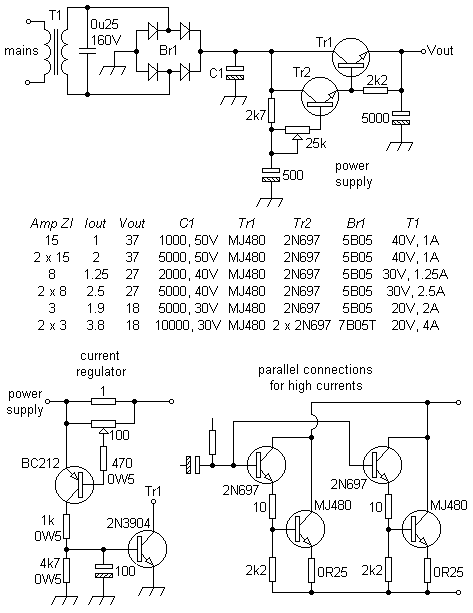
Power supply for 1969 JLH class A amplifier.

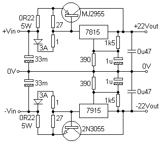
Matching regulator for 1996 JLH class A amplifier, 5V operating differential recommended.

If supply = ±22V +5V operating diff @ 2A quiescent and 3A full load, then (per amplifier) each secondary = 19V @ 5A. For stereo, transformer = 20-0-20V @ 10A = 400VA.
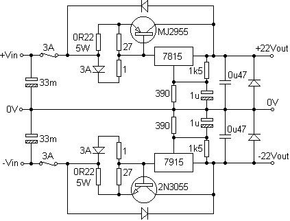
Many manifestations of JLH designs pay scant regard to filtering of the mains supply, felt necessary if mains noise is to be avoided. 3A (or higher) fuses can be placed in the supply lines, between the main smoothers and the regulator. Some diodes (200V, 6A) add robustness for emergencies. 33mF smoothing may seem extravagant, allow 2.2mF (ie 2200µF) for each ampere supplied, minimum. A range of 6.8mF to 10mF seems reasonable. Polycarbonate types can be paralleled with these.

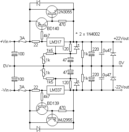
Another regulator arrangement that arguably gives better performance.

Dual LM338K regulators (separate secondaries) have been used. If implementing large capacity smoothing banks, soft-starts will reduce stresses arising from switch-on surges.
especially if you want additional content to this page
or if you find any links that don't work. Don't forget
to add the page title or URL. Take care!
Google search for John Linsley Hood.
Back to index, sound, tips or home.