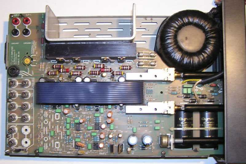
Cyrus 1 integrated amplifierThe Mission Cyrus 1 was for it's size a complex, high quality build that continues to spawn later versions. However, the emphases on innovation, compactness and 'modernity' were felt to detract from the function.
This design used high voltage fast switching devices (BUV28s, TP77 or BUV48 in Cyrus 2) with low saturation voltages in it's quasi-complementary output and an interesting 'soft-clip' feature. Personal preference would have reduced the gain of the PA and the value (470µF) of the feedback's blocking capacitor, a bipolar type that could usefully be paralleled with a decent HF type. For most speaker systems a value of 47-100µF will suffice, a -3dB response of 1Hz being considered over-kill. If such a low response is necessary, then a DC offset and coupling should be considered thus dispensing with the capacitor's non-linearities. Ideally, associated transistor pairs should be matched. In a rebuild, a fully complementary output pair could reduce distortion, especially at low output levels.
The RIAA stage differed interestingly from the norm using low-noise NE5532/4 ICs, as did the innovative case which laid the rear connectors flat so that access from the front was easier. Provision for the use of headphones and equalisation could have been added. A balance swing of only 5dB was considered inadequate by some, separate but ganged volume controls could then have been incorporated.Considerable attention to circuit detail had been made. Virtually all components fitting on a perhaps too compact PCB, access (and air-flow) to the power amplifier circuitry was restricted by the ribbon-cable between the sockets and the input/record selector switches, which perhaps could have been better sited nearer the sockets with longer switch operating shafts.
Requests for power supply data are sometimes received, burnt-out transformers being the commonest complaint, apart from output transistor failure. One circuit diagram gives a spec of 22V3-0-22V3 @ 100VA (3% reg). Toroids of this size are usually specified with a regulation of 10%. With a line rise of 10%, off-load rail voltages will be of the order of ±40V which must be below the operating voltages of the output devices (BUV28 Vceo=200V). The technical data given in the instruction manual for the Cyrus 1 gives a minimum speaker impedance of 8R (3.15AF fuses fitted supplying both PAs, suggesting a safe load of 2.5A) and a continuous average power into 8R of 25W (20V, 2.5A, pk), suggesting a max supply of ±30V, and a 17-0-17V 125VA transformer. Continuous average power into 4R is given as 40W (17.5V, 4.5A, pk), suggesting a max supply of ±28V and a 16-0-16V 200VA transformer. The maximum output level is quoted as 17Vrms (24Vpk or 48Vpk-pk). The reader should find a solution within these limits that will necessarily be limited by the space available within the enclosure.
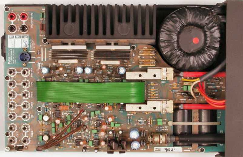
Unfortunately, the enclosure left much to be desired, the plastic top half of which was considered flimsy. Heat-sinking was limited (acknowledged in the instruction manual) with a distinct lack of radiator fins, a commercial constraint perhaps, an issue then addressed in the '2' (although '2' PA layouts and heat-sinks have been seen in otherwise series '1' models), with larger output transistors, a revised RIAA preamp and an add-on power supply for higher power outputs (50W/8R and 80W/4R, 4AF fuses fitted, with PSX added 70W/8R and 125W/4R). Both models offered damping factors (20Hz to 20kHz) of 100. A steel case would have helped with screening and presentation, although nickel or silver loaded paint can be applied to the lid's interior.
The PSX gave an unregulated ±40V supply with a regulated ±18V intended to run a Mission PCM II CD unit. The higher voltage supply which could be used to power the 767 LFAU was smoothed by four 15mF capacitors, compared to the two 10mF in the Cyrus 2, drove the PAs directly, the fuses for which were removed from the amplifier. The amplifier's internal supply then fed the preamp stage. If the phono section was not used, the mains lead could be removed. A DIN female line connector (less shell) will fit the amplifier, however, it is advised that this should be filled with epoxy once secure connections are soldered to give added strength and help prevent shorts.Complex designs can perform well but, if built from commercial grade, with more components there is more to go wrong especially if fundamentals, such as dissipation, are overlooked. A nice little innovative design though, that engenders fondness amongst it's users and favourable comparisons to contemporaries.
Contact me at paulkemble@hotmail.com
especially if you want additional content to this page
or if you find any links that don't work. Don't forget
to add the page title or URL. Take care!
Back to index, sound, tips or home.